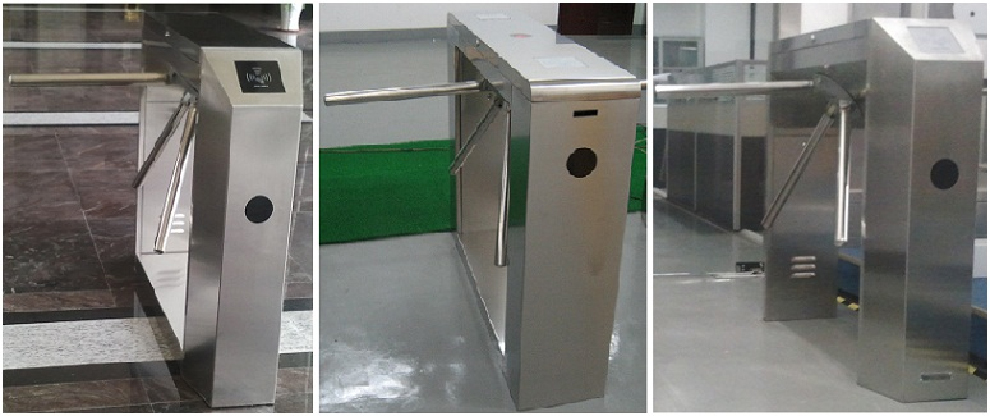
TheTripod Turnstile TR provides a basic but effective, economical tripod for either internal or external installations, with smooth, virtual silent operation.
Users include
Government
Retail
Finance
Telecommunications
Information
Technology
Banking
Publishing
Leisure
Petrochemical
Education
Technical Specification
Orientation
Pass Left or Pass Right
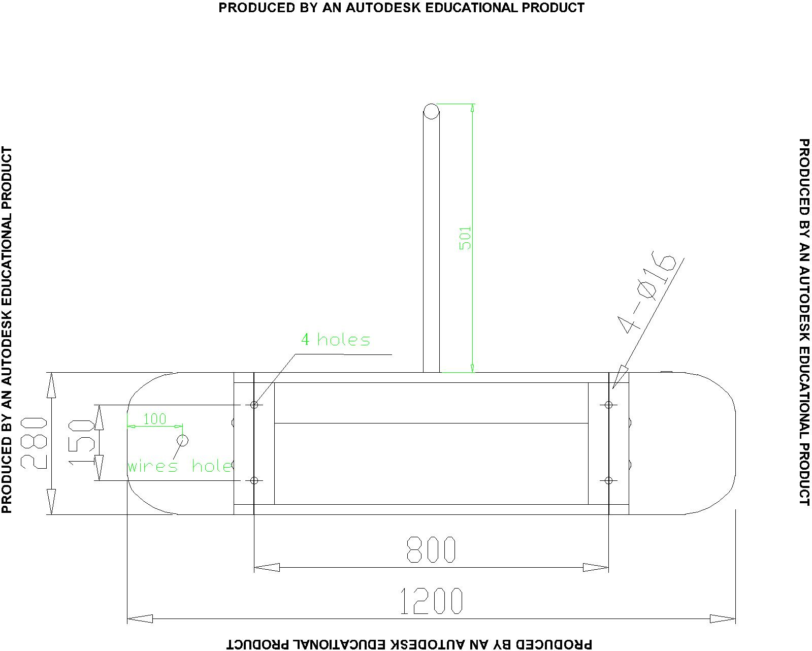
Unit Dimensions
L1200*H1000*W280mm
Walkway Width Standard 550mm
1
Drive
Motorized, Hand operated
Materials
Casework
Casework Lid
Tripod Led
Tripod Arms
#304 Stainless steel
#304 Stainless steel
Cast aluminum with painted grey finish
38mm dia #304 Polished Stainless steel
Function
Passage in both directions, electronically controllable
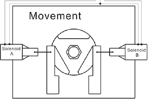
Mechanism
Control of the Tripod operation is achieved by an electro-mechanical head mechanism located within the top section of the turnstile casework. It is silent in rotation and comprises the following standard features:
· A positive lock action that prevents two passages at one time
· A self centering mechanism to ensure complete rotation of the mechanism to the home position
· Anti backup device to prevent reverse rotation once the mechanism has moved 60O from home
Operating Models
The mechanism is locked until a valid authorization signal is received.
Power Failure
In the event of an emergency or isolation of the power supply, the tripod can be configured to fail-safe, i.e. rotates freely. As standard tripods are configured bi-directional fail-safe unless specifically requested otherwise.
Fire Alarm – Input facility available for 0V contact supplied by others to affect the fail state.
Interface
The mechanism is controlled via microprocessor control logic with the following standard features:
· One input for opening/locking the mechanism in each direction
· Two protected outputs for control of the opening/locking solenoids
· Four protected outputs for piloting way mode indicators
· Two protected outputs for counting passage in ether directions
· Two 0V output relays indicating availability of use in either direction or for counting passage in ether direction.
· Two open collector NPN outputs to count passage or to indicate availability of use in either direction or activate the optional drop arm feature.
· One serial port RS485.
Unit has an adjustable time out facility if required i.e. Go signal will be cancelled if passage through turnstile is not completed within pre-set time. The standard default is 8 seconds adjustable via parameter change.
The logic is protected against short circuits, overloads, and polarity inversion. Additional detailed information is available upon request
Power Supply
220V AC 60Hz (50Hz available) the circuit is fed via a remote mounted step down transformer supplied with the unit.
Power Rating
Stand by Less than 0.5 AMP; in operation up to 6.0 AMP
Logic Voltage
24V DC
Standard Operating Models
Switchable via an optional digital touch screen (HMI)
· Enter / Card In
· Exit / Card Out
· Free Exit / Card Out
· Optical or Barrier function
· Pop out Mode
· Closed
· Reset
Status Lights
Pictograms
Accessories and Optional Extras
Alternative Materials, Finishes and Custom Design
· Refer to Proud Entrance Control Inc. for specific material design requirements.
· Alternative top and casework materials.
Card reader Mounting Integration of customer supplied readers into the SW lid.
Lane Lights
· Mounted upon the vertical front section of the SW to act as traffic light flow control, i.e. Green arrow - lane open, Red arrow - lane closed and Flashing Red arrow - lane alarm.
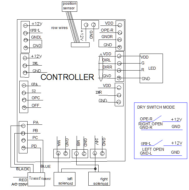
Electronic Circuit Boards(CAD and image file)
The mechanism has three electronic circuit boards:
(1)MAIN BOARD
Board Connectors
Connector P14
Function power supply
1 GND
connecting GND on power supply board and GND on main board
2 24V
DC 24V connecting 24V on power supply board
3 12V
DC 12V connecting 12V on power supply board
4 OFF
Emergency button for arm opening when power off , connecting off on power supply board
Connector P13
Function motor
1 MA
SOLENOID A- OR left
2 GND
GND
Connector P12
Function motor
1 MB
SOLENOID B- or right
2 GND
GND
Connector P11
Function
1 LK+
24V solenoid A and B +
2 LK-
GND EMPTY
Connector P9
Function
1 VDD
DC 12V , empty
2 IN-R
empty
3 GND
empty
ConnectorP8
Function LED Illuminate
1 VDD
DC 12V( LED 12V)
2 DIRL
Illuminates LED green light in left direction(LED G)
3 DIRR
Illuminates LED green light in right direction(LED R)
4 GND
Ground (LED GND)
Connector P7
Function closing door input signal
1 VDD
DC 12V
2 OPEN-R
Arm opening right inputs signal, high level valid (5-12V,200MS),such as dry contact on VDD and OPEN-R is a valid signal, then arm opening
3 GND-R
Ground relatives the Open-R singal ,low level valid.
4 GND
Ground(0 V)
Connector P4
Function openning door input signal
1 VDD
DC 12V
2 OPEN-L
Arm opening left inputs signal, high level valid (5-12V,200MS),such as dry contact on VDD and OPEN-L is a valid signal, then arm opening
3 GND-L
Ground relatives the Open-L singal ,low level valid.
4 GND
Ground(0 V)
Connector P3
Function door openning position sensor
1 VDD
DC 12V empty
2 IN-R
empty)
3 GND
empty
ConnectorP2
Function open, close, anti crack signal
1 OPA
empty
2 S2
empty
3 OPC
empty
4OFF
empty
Connector P1
Function transformer
1 PD
AC 20V blue
2 PC
AC 20V blue
3 PB
AC 13V black
4 PA
AC 13V BLack
Magnatic sensitive switch
Connector
Function
1 S1
Empty
2 S2
Position sensor connecting controller, low level valid.L5 light
3 GND
0V
4 V+
12V
5 S3
Empty
The mechanism has three electronic circuit boards:
(1) MAIN BOARD
Programmable Parameters
Adjustable Auto Re-Lock Time-push the ‘SET’ button on mainboard until the ‘P0’ is displayed in the led and you hear a beep. Then push the ‘INC’ button the ‘P1’ will be displayed in the led.now push the ‘SET’ to confirm you select this function for setting relock time and the ‘00’ will be displayed in the led, then push ‘INC’ to add one sencond, push ‘DEC’ to minus one second, in the end push the ‘SET’ to confirm the auto relock time.
Card Reading W/O Memory-It has a function of card reader with or without memory, and it may be set up with the built-in small keyboard in accordance with the requirements of the users, push the ‘SET’ button on main board until the ‘P0’ is displayed in the led and you hear a beep. Then push the ‘INC’ button the ‘P02’ will be displayed in the led.now push the ‘SET’ to confirm you select this function for setting relock time and the ‘00’ will be displayed in the led, then push ‘INC’ to add one sencon, push ‘DEC’ to minus one, in the end push the ‘SET’ to confirm memory status,00 shows flap barrier opening with memory,01 shows flap barrier opening without memory,
Installation
Material preparation
1)φ14 cores 2.5-3m
2)M12 screw 4pcs
3)M5 Hexagon wrench、M12 Screw wrench、 screwdriver
Installation of Unit
1)Schematic of installation requirements, make sure holes, embedded in the installation position Department of land 4 feet M12 screws, or expansion screws.
2)A level concrete floor is required to ensure proper installation recommended depth is at least 4 inches. Fixed gates when the gates place good